
What Causes String Imbalance in 48V DC Racks
String imbalance is the gradual divergence of behavior between the series and parallel branches of a battery string. In a healthy 48V rack, every cell and module shares current and voltage as one unit. Over time, small physical and chemical differences push each branch onto its own trajectory, and the trajectories keep separating. Pack voltage can still read as acceptable while individual branches drift apart.
The mechanisms are cumulative, which is why routine monitoring misses them:
- Cell capacity mismatch – Manufacturing tolerances mean no two cells hold identical amp-hour capacity. In a series string, the lowest-capacity cell sets the usable limit and reaches its voltage cutoffs first on every cycle.
- Uneven module aging – Modules age at different rates depending on their history, so internal resistance rises at different speeds across the string.
- Wiring and busbar resistance differences – Cable length, lug quality, and busbar geometry add small, unequal resistances that shift current sharing between parallel branches.
- Terminal and interconnect torque variation – A loose or over-tightened terminal changes contact resistance and creates a localized voltage drop under load.
- Temperature gradients across rack positions – Top, middle, and bottom slots run at different temperatures, and reaction kinetics and self-discharge track that heat.
- Uneven charge/discharge cycling – Branches closer to the load or charger carry more current, so they cycle harder than their neighbors.
These factors compound rather than cancel. A warm branch with slightly higher resistance draws less current, cools unevenly, and ages differently, which widens the gap further each month.
The practical consequence for 48V DC systems is direct: divergent branches trigger BMS alarm chatter, force the balancer to work against a widening offset, and cut usable runtime even when the pack looks healthy. Engineers who understand these root causes can tell normal drift from a failing module and time replacements before fleet maintenance schedules are disrupted. Catching string imbalance early preserves capacity and avoids premature module swaps.
Diagnosing String Imbalance: Measurement and Analysis
On a 48V DC rack, imbalance is a current problem before it becomes a voltage problem. When parallel strings stop sharing load equally, one string carries more current than its neighbors. That string heats up, ages faster, and drifts further out of balance on every cycle. By the time the BMS raises a voltage alarm, the current sharing fault has usually been running for weeks. Measure the load split first; the voltage readings will follow.
Confirm string imbalance with five core tests, and log each one against a fixed reference so you can trend it.
- Per-string current: record amps per string at rest and under load, using a calibrated shunt or clamp meter.
- Cell group voltage: record millivolts per group to expose the weakest group inside each string.
- Series-block voltage: record total volts across each block to compare blocks within the string.
- Internal resistance: record milliohms per cell on a schedule to catch rising resistance before it shows on the load test.
- Impedance / conductance: record per-cell values to flag cells that resist current flow differently from their neighbors.
Per-string logging gives you the raw trace. Cell group and series-block comparison localizes the fault, and current sharing across parallel strings quantifies how uneven the load distribution has become. Internal resistance trending and impedance/conductance testing tell you whether the imbalance is a wiring problem, a weak cell, or a string that has aged out.
Do not judge severity from a single reading. Compare each string against the fleet average and calculate the deviation as a percentage. As a working rule, a string more than 10 percent off the average current split, or a cell group more than 50 millivolts off its peers, belongs on the action list rather than the watch list. Track the rate of change: slow drift is a maintenance item, fast drift is a module swap.
Quick reference: what to record
| Measurement point | Metric to record |
|---|---|
| Per-string current | Amps per string (rest and load) |
| Cell group voltage | Millivolts per group |
| Series-block voltage | Volts per block |
| Internal resistance | Milliohms per cell |
| Impedance / conductance | Per-cell value |
Log these five metrics over time. The trend, not the snapshot, tells you how severe the string imbalance is and whether a 48V DC string needs balancing, rework, or replacement.
| Symptom Observed | Likely Root Cause | Corrective Action |
|---|---|---|
| One string drifts low under load while parallel strings hold voltage | Higher series resistance or a weak cell in that string, so it sags first as current divides unevenly | Measure per-string voltage and current under a known load; flag the outlier string and clamp-test its weakest block |
| Unequal absorption current between strings | Divergent state of charge or mismatched string voltage reaching the absorption setpoint at different times | Recharge all strings to full, equalize float/absorption setpoints, and verify each string hits target current within tolerance |
| Rising internal resistance in one module | Cell aging, sulfation, or a degrading terminal weld driving IR up over service life | Trend module IR against baseline; replace the module when IR exceeds the rejection threshold or spreads beyond peers |
| Temperature skew across a rack | Poor airflow, blocked vents, or a hot spot from tight spacing causing uneven heat rejection | Recheck rack spacing and airflow path, clear obstructions, and relocate or fan-cool the hot module to bring cells within a few degrees |
| Loose or high-resistance interconnect | Insufficient terminal torque, corrosion, or a failed lug raising joint resistance | De-energize, clean and re-torque terminals to spec, and replace any pitted or heat-discolored interconnect hardware |
| Premature end-of-discharge on one string | One string reaches cutoff before others, usually from a weak block or lower capacity | Confirm capacity with a discharge test on the offending string; replace weak blocks or retire the string if it cannot meet runtime |
| String current imbalance worsening over weeks | Progressive cell degradation or a self-discharging module pulling the string low at rest | Log rest-state voltages over time, isolate the self-discharge module, and swap it before it drags the whole string |
| BMS repeatedly flagging voltage deviation alarms | Sensor/lead resistance offset or a genuinely imbalanced segment near the threshold | Cross-check with a calibrated meter; recalibrate sense leads if reading is false, otherwise address the real imbalance |
BMS Alarm Chatter: Why Alarms Toggle Repeatedly
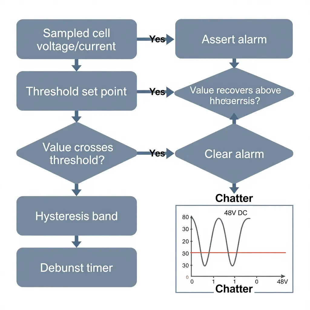
BMS alarm chatter is the rapid, repeated asserting and clearing of an alarm by a battery management system. Instead of latching once and holding, the alarm state flips on and off, sometimes dozens of times per minute, while the underlying cell and pack conditions barely move. On 48V DC rack systems, chatter is more often a configuration or signal-integrity problem than a genuine hardware fault.
Chatter lives at the boundary between a measured value and its configured threshold. When the operating value sits close to that threshold, measurement noise, load steps, or sampling artifacts can push the signal back and forth across the trip point.
Six causes show up repeatedly:
- Threshold values set too close to normal operating values, leaving almost no margin.
- Hysteresis and debounce windows configured too tightly, so the alarm re-arms before the value stabilizes.
- Noisy voltage or current sampling from sensor drift, poor grounding, or high-impedance sense leads.
- Imbalance-induced voltage sag under load, where string imbalance drives the weakest module below threshold during transient current draw.
- Poor CAN or RS-485 integrity: dropped frames, missing terminators, or bus reflections that delay or corrupt status updates.
- Firmware polling or filtering issues, such as slow scan rates or aggressive filters that sample during switching transients.
Persistent chatter degrades the value of the whole alarm system. Operators start ignoring alerts, controllers latch nuisance faults or trip contactors unnecessarily, and genuine events get buried under repeated toggling. Auditing threshold margins, widening hysteresis, and cleaning up sampling and bus integrity usually resolves the condition without replacing any module.
48V DC Rack Battery Architecture: The Schematic
The rack schematic is a deliberately minimal, two-dimensional drawing rather than a photograph, and its only job is to make system topology legible at a glance. It shows what an engineer would sketch on a whiteboard before wiring a real cabinet.
What each element represents
- Vertical rack frame – the tall outer rectangle that stands for the physical enclosure holding the module stack.
- Stacked module blocks – the row of smaller rectangles inside the frame. Their alignment shows how cells group into modules, and how modules group into series and parallel strings to reach the 48V nominal rail.
- Interconnect busbars – the heavier horizontal and vertical lines bridging module terminals. These carry load current and define the string path.
- Positive and negative rails – the twin lines along one side, marking where the string connects to the DC distribution point.
- BMS block – the compact block beside the rack: the sensing and communication brain of the pack.
- Sense lines – the thin lines branching from every module back to the BMS. Each one is a voltage tap monitoring a single module’s health.
- Communication bus – the single line leaving the BMS toward the top of the frame, representing the data link to the controller or alarm system.
Where imbalance and sensing happen
Imbalance is a topology problem, and the drawing shows where it hides. Every sense line ends at a sensing node (drawn as a small circle or square) on a module terminal. When one module drifts in voltage relative to its neighbors in the string, the BMS reads it as a divergence between adjacent taps, and that divergence is what eventually triggers the alarm chatter operators know. The triangle symbols placed along the strings mark representative imbalance points, the spots most likely to sag first under load.
A weak module never fails in isolation; it drags its neighbors with it. That is why the diagram places sensing position and string position so close together. Reading that layout is the first step in deciding whether to rebalance or replace, the same discipline that keeps any critical power asset running, whether it is a battery string or a fleet under constant maintenance.
How to read the layout
Work from the rails inward: current flows through the busbars, voltage is sensed at the taps, and intelligence flows through the communication line. Trace those three paths on the drawing and you can trace them in the cabinet, which tells you where a module swap will actually help.
Troubleshooting BMS Alarm Chatter
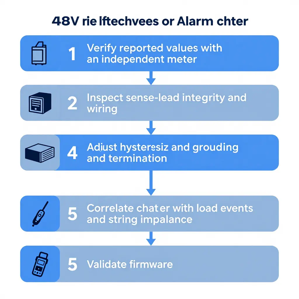
Alarm chatter is the rapid, repeated toggling of a BMS alarm between its set and clear states. The rule that should guide every fix: chatter is almost never caused by the fault the alarm names. A genuine overvoltage or over-temperature condition holds steady and clears only when the root cause is resolved. Chatter, by contrast, is repetitive, self-clearing, and usually tied to timing, thresholds, or signal integrity. Treat it as a measurement problem first and a protection problem second.
Work the evidence in order. Verify actual versus reported values with an independent meter; if the meter and the BMS disagree, the sense path is suspect. Check sense-lead integrity and wiring, since loose lugs, oxidized terminals, and shared or mis-ordered leads are common culprits. Adjust hysteresis and debounce settings within safe limits so a signal must persist before it triggers. Confirm communication grounding and termination, because floating or double-terminated buses generate erratic frames. With clean signals, correlate chatter with load events and string imbalance, as a weak module sags under load and drags its string voltage with it. Finally, validate firmware behavior to rule out stale logic or known bugs.
Configuration parameters to review:
- Overvoltage and undervoltage trip points
- Hysteresis bands for voltage, current, and temperature
- Debounce pickup and drop-out delays
- Cell voltage delta and string imbalance thresholds
- Temperature alarm and recovery setpoints
- SOC reset and calibration points
- CAN/RS-485 baud rate, node address, and termination
Log alarm timestamps alongside load and current data for at least one full cycle before changing any hardware. Most BMS alarm chatter resolves through correct hysteresis, clean sense leads, and proper bus termination; replace a module only when string imbalance persists under matched load.
String Imbalance Trend in a 48V DC Rack Battery Backup System
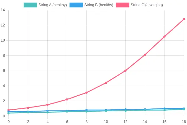
X-axis: Time (months, 0-18)
Y-axis: String Imbalance (%)
Series: String A, String B (both healthy), String C (diverging)
| Time (months) | String A (%) | String B (%) | String C (%) |
|---|---|---|---|
| 0 | 0.4 | 0.6 | 0.8 |
| 2 | 0.5 | 0.6 | 1.1 |
| 4 | 0.5 | 0.7 | 1.5 |
| 6 | 0.6 | 0.7 | 2.2 |
| 8 | 0.6 | 0.8 | 3.1 |
| 10 | 0.7 | 0.8 | 4.4 |
| 12 | 0.7 | 0.9 | 6.0 |
| 14 | 0.8 | 0.9 | 8.1 |
| 16 | 0.8 | 1.0 | 10.5 |
| 18 | 0.9 | 1.0 | 12.8 |
Caption: Strings A and B hold at or below 1% imbalance across all 18 months, while String C climbs steadily from 0.8% at month 0 to 12.8% at month 18. The widening gap points to a degrading cell or module inside a single string; the healthy strings show the fault is local to one string rather than a system-wide charging issue. The 5-6% imbalance threshold is crossed around month 11 here, which typically coincides with the BMS triggering repeat alarms and is the practical cue to isolate and swap the affected module before the imbalance accelerates.
When to Swap a Module: Decision Criteria
Replace a module when remediation has already been tried and the defect is structural rather than operational. Swap a module when the fault is internal and irreversible; retain it when the deviation is a system-level imbalance that balancing can still correct. In a 48V DC rack battery backup, the goal is not the lowest reading but a string that delivers its rated capacity under load. A module that fails that test after proper intervention is a replacement candidate.
Quantitative Evidence
Base decisions on measured thresholds, not isolated alarms.
- Persistent capacity loss below specification. If a module holds under 80% of nameplate capacity across three full discharge cycles – even after a complete top-balance – the loss is permanent and the module cannot support the string.
- Internal resistance above a defined limit versus sibling modules. Measure DC internal resistance at consistent temperature and state of charge. A module running more than 1.5x the median of its siblings is degrading faster and will drag the whole string down.
- Repeated imbalance after balancing attempts. If string imbalance returns within 30 days of a controlled equalization, the weak module is the root cause and balancing is only masking it.
- Cell-level anomalies. Visible swelling, casing distortion, or voltage collapse under load – a cell dropping below the low-voltage cutoff during a normal load step – indicates a failing cell that no amount of cycling will recover.
- Verified safety or thermal events. Any recorded thermal runaway signature, electrolyte leakage, or sustained over-temperature event justifies immediate removal, not reconditioning.
Swap Versus Retain: Quick Criteria
- Swap: capacity permanently under 80% of spec after cycling.
- Swap: internal resistance over 1.5x the sibling median.
- Swap: imbalance recurring within 30 days of balancing.
- Swap: swelling, leakage, or load-induced voltage collapse.
- Swap: any verified thermal or safety event.
- Retain: one-off deviation corrected by a single documented balancing cycle.
- Retain: deviations traced to wiring, connectors, or BMS sense leads rather than the cell.
Recommendation
Once a module meets any swap threshold above, replace it with a matched unit of equal chemistry, capacity, and age profile, then re-verify the full string under load. Retaining a degraded module to save cost only shifts the failure outward and shortens the life of its neighbors. For teams managing backup assets alongside vehicle fleets, the same disciplined maintenance logic applies.
Mapping the Swap Decision: Reason First, Conclusion Second
Swapping a module in a 48V DC rack battery is not a gut call. It is the endpoint of a short chain of reasoning, and the flowchart below captures that chain. Read it top to bottom and you follow the logic an engineer should follow: detect the problem, test a cheaper fix, judge the outcome, and only then commit to a replacement.
Here is how the node layout works, so you can narrate the path as you work through a real rack.
Node layout
- Start node (top circle). The flow begins the moment the system flags an abnormality in the string: a rising cell-to-cell voltage spread, a capacity drift, or the first BMS alarm. A single straight arrow drops from it.
- First diamond (decision). The imbalance-detection checkpoint. Once imbalance is confirmed, the arrow continues downward rather than branching sideways.
- Rounded rectangle (process). The balancing attempt. It is a process box because it is an action, not a question: run the balancing routine, equalize the cells, and let the BMS do its job. A downward arrow leads out of it.
- Second diamond (evaluation). The pivot of the diagram, where you evaluate the post-balance result. Two angled arrows leave it, one to the left and one to the right.
- Two side rectangles (outcomes). The left branch leads to a rectangle representing the decision to retain the module; the right branch leads to one representing the decision to replace it.
- Terminal nodes (small circles). Each side rectangle closes with a short arrow into a terminal circle, ending the workflow for that path.
Connector flow
A single vertical spine of arrows runs from the start circle through the detection diamond and the balancing box into the evaluation diamond. That straight spine is the “reason” phase, where you gather evidence before making a costly move. Only after the evaluation diamond do the arrows split, fanning outward to show that the conclusion is a two-way choice. The split is symmetrical because retaining and replacing carry equal weight until the evidence pushes you one way or the other.
The diagram also rules out a common field mistake. Technicians sometimes jump from the first alarm straight to a module swap, skipping the balancing attempt and the evaluation step. The flowchart forbids that shortcut literally: the replace branch is only reachable after the balancing box and the evaluation diamond.
Why the order matters
Balancing is cheap, fast, and reversible; replacing a module is none of those things. Putting the balancing attempt before the evaluation diamond encodes a cost-aware sequence: exhaust the low-impact remedy, then measure, then escalate. If the string self-corrects and holds voltage under load, the left branch fires and you retain the module. If the imbalance snaps back or a cell refuses to recover, the right branch fires and the module is retired.
Keep this flow in front of you the next time a rack starts chirping. It turns a stressful alarm into a repeatable procedure and keeps you from spending a module budget on a problem that balancing could have solved.
Module Swap Readiness Checklist
Before pulling a module from a live 48V DC rack, work through this sequence in order. Each step builds on the one before it, and skipping ahead is how a routine swap turns into an arc-flash report.
- Isolate and de-energize the target string. Open the string disconnect, lock out the DC breaker, and verify zero volts with a calibrated meter before you touch any terminal.
- Record baseline string voltages. Log individual module voltages, string current, and ambient temperature so you have a documented reference to measure the post-swap result against.
- Verify replacement module compatibility. Match the replacement against the existing bank on chemistry, nominal capacity, and cycle age, because mixing dissimilar cells accelerates the very imbalance you are trying to fix.
- Confirm torque specifications. Look up the manufacturer’s terminal torque value and stage the correct calibrated wrench so every connection meets spec instead of guesswork.
- Sequence the reconnection. Reattach terminals in the prescribed order, respect polarity, and keep the string isolated until every interconnector is fully seated and torqued.
- Re-run the balancing routine. Trigger the BMS balancing cycle and watch for convergence, so the new module settles into the string rather than fighting the rest of the bank.
- Monitor for 24 hours. Track voltage spread, string current, and temperature trends for a full day to catch early drift, thermal hot spots, or renewed BMS alarm chatter.
- Document the change for the maintenance log. Record the module serial number, swap date, torque value used, and post-swap readings so the next technician inherits an accurate history.
Where 48V DC Rack Backup Matters in Commercial and Fleet Operations
In a high-throughput car wash or a vehicle depot, the electrical load never truly rests. Entry gates cycle, plate cameras read every vehicle, dosing pumps meter chemicals, and point-of-sale terminals stay live from the first car to the last. A 48V DC rack battery backup holds that chain together through grid blips, brownouts, and generator transfer delays. Continuity is not a property of the equipment; it is a property of the backup string. When the string is healthy, a utility event is invisible to customers and staff. When it is not, the lane stops, and a stopped lane is revenue that never comes back.
Sites that fold the rack into a routine fleet maintenance rhythm generally catch degradation early. Sites that don’t tend to discover it during the busiest hour, when a contactor drops out mid-cycle.
Operational continuity considerations for commercial sites:
- Verify string voltage and state of charge on a fixed cadence, not only after a fault
- Tune BMS alarm thresholds deliberately, so warnings stay meaningful instead of constant
- Stage one known-good spare module on site so a swap is a scheduled task, not an emergency
- Document which loads sit behind the rack so nobody learns the hard way
String imbalance and BMS chatter are the two most common paths from a healthy rack to a down site. In a series string, the weakest module sets the ceiling for the whole pack: one module drifting a few hundred millivolts below its neighbors lowers usable capacity, accelerates further drift, and shortens runtime exactly when the load peaks. BMS chatter follows. Repeated over-voltage and under-voltage alarms, contactor cycling, and self-clearing faults train busy operators to ignore the warnings meant to protect them, and a conservative BMS tripping offline looks identical to a hard failure at the register.
Operators who treat uptime as a competitive edge, the way many approach maximizing fleet value, manage the rack actively rather than reactively.
If throughput pays the bills, the 48V DC rack battery backup deserves the same planned-maintenance discipline as the vehicles it serves. Measure balance, trend it over time, and swap the outlier module before the BMS makes that decision for you.
Key Takeaways for 48V DC Rack Battery Engineers
Three points belong in every maintenance playbook.
First, string imbalance is a gradual, measurable divergence, not a sudden event. It develops as cells age, connections corrode, and self-discharge rates drift apart. Because the process is slow, trend monitoring catches it: log per-string voltage and current over weeks and watch the slope rather than a single snapshot.
Second, BMS alarm chatter usually reflects a configuration or sensing problem rather than a fundamental failure. Loose sense leads, conservative thresholds, and mismatched firmware generate far more noise than genuine cell faults. Before condemning a battery, verify the wiring, calibrate the sensors, and review the alarm logic.
Third, decide when to swap a module using objective, threshold-based criteria – capacity fade, internal resistance, and voltage deviation against documented limits – never the loudest alarm or the most recent complaint.
Reliable 48V DC rack battery backup depends less on any single component than on consistent measurement and disciplined decisions.
Action points to carry forward:
- Baseline every string and log voltage and current trends weekly.
- Audit BMS thresholds and sense wiring before escalating any alarm.
- Define written replacement thresholds and apply them uniformly.
- Document each intervention so patterns become visible over time.